Suche BMS-Schützansteuerung für CityEL
- Themenstarter aringo
- Datum Start
Du verwendest einen veralteten Browser. Es ist möglich, dass diese oder andere Websites nicht korrekt angezeigt werden.
Du solltest ein Upgrade durchführen oder ein alternativer Browser verwenden.
Du solltest ein Upgrade durchführen oder ein alternativer Browser verwenden.
Bis zu 350 € für alle Fahrer von Elektroautos!
» Jetzt die höchste Quote am Markt sichern
» Oder direkt FIX 85 € erhalten.
Bereits jetzt THG-Quote für 2024 beantragen! Sichere dir deinen Quoten-Anspruch bevor die Prämie sinkt!
Hey Rick ... trotzdem besten Dank....
hab die Resistoren ausgetauscht - und.... funzt wieder!
Es waren zwei Ersatzwiderstände anbei (in dem Gehäuse), die sich wohl durch einen Aufprall gelöst haben und diesen Umstand verursacht haben... dieses Problem ist schonmal gelöst...
Sonnige Grüße aus Alfeld bei Hannover,
Oliver
hab die Resistoren ausgetauscht - und.... funzt wieder!
Es waren zwei Ersatzwiderstände anbei (in dem Gehäuse), die sich wohl durch einen Aufprall gelöst haben und diesen Umstand verursacht haben... dieses Problem ist schonmal gelöst...
Sonnige Grüße aus Alfeld bei Hannover,
Oliver
Oh endlich mal wieder jemand aus der "nähe"! Hier im "Norden" sind die El Leute ja dünn gesät.
Viel Spaß und Erfolg weiterhin mit deinem El
Grüße aus Peine
Fabi
Viel Spaß und Erfolg weiterhin mit deinem El
Grüße aus Peine
Fabi
Hey Fabi!
Ja, das hab ich auch gemerkt - habe den City El in Süddeutschland in der Nähe von Trier gekauft und .... bin bin damit nach Alfeld gefahren (ca. 400km)") Geile Tour, war sehr abenteuerlich - viele tolle Menschen unterwegs kennengelernt - und bei 45kmh natürlich einige Tage gebraucht zuguterletzt traten leider diese Fehler auf, ADAC Plus sei Dank...
Geile Tour, war sehr abenteuerlich - viele tolle Menschen unterwegs kennengelernt - und bei 45kmh natürlich einige Tage gebraucht zuguterletzt traten leider diese Fehler auf, ADAC Plus sei Dank...
Sonnige Grüße!!
Ja, das hab ich auch gemerkt - habe den City El in Süddeutschland in der Nähe von Trier gekauft und .... bin bin damit nach Alfeld gefahren (ca. 400km)
Geile Tour, war sehr abenteuerlich - viele tolle Menschen unterwegs kennengelernt - und bei 45kmh natürlich einige Tage gebraucht zuguterletzt traten leider diese Fehler auf, ADAC Plus sei Dank...Sonnige Grüße!!
Hi there,
Glad to hear you managed to fix it!
I may have one spare if ever. I removed the old BMS from my Cityel and installed a Daly BMS instead. Unfortunately my CityEl does not appear to agree with the change and I can no longer start it… should I remove the old BMS altogether? I have of course removed all the connections to the batteries.
thanks for your help,
Cheers,
Greg
I can no longer start it… should I remove the old BMS altogether? I have of course removed all the connections to the batteries.
If by "old BMS" you mean the Boostech-Boards, you will at least have to remove or bridge the relais which breaks the circuit if the (old) BMS detects a critical battery-failure.
As far as I know this relais should be mounted under the seat or under the dashboard.
I have a similar problem right now: one of the slave-boards (the ones on the Batteries) is defective, so the BMS thinks one battery-cell is broken (although it really is completely fine) and cuts electricity to the curtis. So no more driving for me until the new board arrives.
Maybe the Daly-BMS also has a relais-connector - maybe then you can just rewire that, especially if the drivetrain is wired "around" the BMS as for the very high currents.
Hope that helps a little.
Thanks a lot @Kamikaze !
This does help a lot indeed. I had tried so many things but thought it may have to do with the “old” BMS. So I will focus on this then.
As I am a bit of a noob what would be the easiest in your opinion? Removing or bridging it? If I bridge it, would it be OK if I bridge at the end of the cables - the yellow and blue ones?
ps - this is an old picture, and confirm that I have changed the batteries and removed the individual modules above the batteries since but still have those cables hanging lose.
Thanks!!

This does help a lot indeed. I had tried so many things but thought it may have to do with the “old” BMS. So I will focus on this then.
As I am a bit of a noob what would be the easiest in your opinion? Removing or bridging it? If I bridge it, would it be OK if I bridge at the end of the cables - the yellow and blue ones?
ps - this is an old picture, and confirm that I have changed the batteries and removed the individual modules above the batteries since
but still have those cables hanging lose.Thanks!!
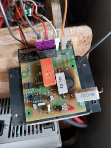
I have never seen these modules! Is it with a microcontroller or with an opamp? The 4-pin device looks like an optocoupler. The one with the heatsink on it maybe a transistor or mosfet for balancing. Adjustable voltages! Looks interesting! I think its analogue, means with an opamp. The wiring could be a parallel connection of all optocouplers outputs, allowing the on-cell units to switch off the motor controller's control voltage.
If you have a number oft the 8-pin IC, I could probably check or repair the units.
If you have a number oft the 8-pin IC, I could probably check or repair the units.
Thanks for your input @Iaase !
I believe these were indeed custom made by the former owner - who was experienced in electronics.
Should these modules be of interest to you, I would happily given them to you and be happy to mail them to your place - as I will no longer need them.
I believe these were indeed custom made by the former owner - who was experienced in electronics.
Should these modules be of interest to you, I would happily given them to you and be happy to mail them to your place - as I will no longer need them.
Mich würde interessieren, was Ihr von dieser Art von massiver Schaltungsbefestigung haltet . GFK gegen Batteriepole?
I am thinking of thermal and mechanical stress for the soldering joints. Undiscovered cold joints? Durability and rigidity may not be the same?
I am thinking of thermal and mechanical stress for the soldering joints. Undiscovered cold joints? Durability and rigidity may not be the same?
Ja, die Befestigung ist suboptimal.
Eigentlich macht man das 'andersherum'. Also an der Akkuzelle ist schon ein Stück Gewindestab, das herausschaut. Da schraubt man dann mit ner Mutter die Öse vom Kabel fest, und obendrüber mit zwei Unterlegscheiben die Platine in der Reihenfolge 'Mutter von Kabelschuh' - 'Unterlegscheibe' - 'Platine' - 'Unterlegscheibe' - 'weitere Mutter'. Die obere Mutter muss man dann auch nicht ganz so fest anziehen, ist ja nur die Platine dran.
Gruß,
Werner
Hier mal die Fortführung einer Unterhaltung, die ich nicht im privaten Teil weiterführen, sondern eure Kommentare darauf hören wollte. Bei Greg(ster) scheint ein selbst-entworfenes "Auf-Zell-BMS" mit dem Temperatuirsensor-Eingang des originalen (?) Ladeprints gekoppelt worden zu sein. Für mich stellt sich die Frage, ob das übertagene "Voll"-Signal digitaler oder analoger Natur ist. Meinem Anschein nach könnte es analog sein, da auch die BMS-Platinen irgendwie analog aussehen (Einstellregler!)
Hi Greg,
thanks for the video! I know a little french but not enough to follow your speech ...
But the things are very clear to me: you have NO sophisticated special charging system, but the very basic first charger, the so called "Trafolader" (transformer charger) together with a "Ladeprint" (charging PCB-board under the seat). That is all "series" and nothing special. In this way, the El was built several hundred times until the beginning 2000's. Mine from '91 had the same setup, but I soon replaced it by three separate "switch-mode" chargers, each for one lead acid batt in this time. Now I have just one modified Meanwell 1.5kW switch-mode power supply near/under the seat that charges 13 Winston LFP cells.
The only one modification to the system I could detect in your video was that the pre-owner seemed to use the wires of the former temperature sensor ("NTC sensor") to tell the "ladeprint", that one or more of the cells is fully charged. I dont know a lot about programming options of the "Ladeprint", but maybe it's possible to programm the controller in a way that charging is switched off, when a signal from the on-cell boards is coming ("normal logic") or missing ("fail-safe" logic). Maybe that was done in your case.
In case the signal is digital, you could test with just shorting the 2 wires (blue and yellow) and see whats happening. (Of course the battery has to be wired and it's voltage is "seen" at the "Ladeprints'" terminals.) Then it's possible to wire your Daly to switch off charging in the same way (but to this later, after you made the described test).
If the signal from the cell boards to the "Ladeprint" was analogue then it's more complicated and would, in my eyes, directly lead to the need of a new charger/charging system, because not many are still able to reprogram the "Ladeprint". In this case you better ask for a new replacement charger in the forum. I can't recomend my solution, because you need to "tinker" a lot in order to use the 1.5kW Meanwell supply as a "constant current - constant voltage charger".
So I would go like this:
- wire your battery cells (if not already done)
- check, that the battery voltage is "visible" from the "Ladeprint" (one cooling/metal sheet is positiv, the other one is negative)
- leave the rest wired original (eg. connection to the "Kapamesser", the capacity measuring unit)
- connect a 47k resistors between yellow and blue
*- Put the "trafo" on (plug in the charger)
- check the display lights: what happens/which one is glowing?
- is the charging starting?
- if not, replace the resistor by a 10k one, return to *
- if not, replace by 1k, return to *
- at least, replace by 100 Ohm and then 12 Ohm and return to * (don't go less than 12 Ohm to prevent burning anything!)
if none of the resistors are showing an effect, I would tend to throw the Trafo and the "Ladeprint" out and replace it with a modern charger. But let's first see your result.
Best, Lars
Hi Lars,
First of all, let me thank you for all your detailed explanations! You are a legend!
Tried the suggested fixes but unfortunately still no succes :'(
Any help or suggestions would be greatly appreciated! I hope it is nothing too major.
Thanks again!
Greg
First of all, let me thank you for all your detailed explanations! You are a legend!
Tried the suggested fixes but unfortunately still no succes :'(
Any help or suggestions would be greatly appreciated! I hope it is nothing too major.
Thanks again!
Greg
Zuletzt bearbeitet:
Hi,
if you have the Kappamesser in you EL, this thing can block driving if it thinks the batteries are empty.
A detailed explanation (in german) is here:
 elweb.info
Short Version: To disengage the blocking, you must short Kapazitätsmesser PIN 13 und 14 like in the first pictures.
Maybe this helps to start driving... But you should really find a mechanical solution for the free standing cells...
Greetings,
Werner
if you have the Kappamesser in you EL, this thing can block driving if it thinks the batteries are empty.
A detailed explanation (in german) is here:
kapazitaetsmesser [elweb]
elweb.info Short Version: To disengage the blocking, you must short Kapazitätsmesser PIN 13 und 14 like in the first pictures.
Maybe this helps to start driving... But you should really find a mechanical solution for the free standing cells...
Greetings,
Werner
Hi Werner,
Thanks for having provided me with this lead! I will check it out. Thanks.
My Kappamesser looks a little different but I will locate the relevant pins:

Regarding the free standing cells, this is only to get the car running. As soon as it is, I will pack them together as I have seen some do in the forum for sure.
All the best
Greg
Thanks for having provided me with this lead! I will check it out. Thanks.
My Kappamesser looks a little different but I will locate the relevant pins:
Regarding the free standing cells, this is only to get the car running. As soon as it is, I will pack them together as I have seen some do in the forum for sure.
All the best
Greg
In your picture i cant locate a Kappamesser .... only The old LADEPRINT , Th DC DC Wandler and The STROMBEGRENZERPLATINE in an unusual position . The blue and yellow wire which went originally to the temperature sensor is now signed BMS ? maybe taken for another purpose.
it would be the best to ask Roger Stoll ( EAT Stoll) maybe he has done the changes. 2007
it would be the best to ask Roger Stoll ( EAT Stoll) maybe he has done the changes. 2007
Zuletzt bearbeitet:
Neue Themen
-
- Ladegerät 121ME221 Onboard Charger Unit im Aixam Mega Multitruck defekt.
- Gestartet von Smilie
- Antworten: 2
- CityEl fährt nur vorwärts / "Ladeprint" brücken
- Gestartet von Markus90
- Antworten: 35
-

Neueste Beiträge
-
-

-

-
 Sinsheim "Treffen alternativer Antriebsformen" am Museum 28.04.2024
- Letzte: wolfgang dwuzet